Drone detection
The frame is divided into a grid of sky areas, and each neural network responds independently: clear or foreign object. The zone knows its sky – clouds, sun, roof edge, and mast.
It detects contrast, not shape. A dark object in a clear sky is visible from two pixels, which corresponds to up to two kilometers.
The zone number indicates the direction, order, and timing of transitions – angular speed, object growth in the frame – is it approaching or passing by.
The drone has a straight course, while the bird is circling. The decision is made based on the entire track, not just a single frame.
01 Why is this necessary?
The distribution center consists of tens of thousands of square meters of roof space, an open area with equipment, a loading zone, and insured goods. Everything is exposed to the elements, and no one is watching from beyond the fence.
The perimeter is secured with fences, cameras, security personnel, and access control, while the air is completely open. However, it is from this area that the most valuable activities take place: reconnaissance flights before a theft, filming internal logistics, dropping goods onto the property, or damaging the roof or equipment.
Radio detectors pick up the drone's communication with the remote control. For them, a drone following a pre-programmed route with its transmitter turned off is simply non-existent. The camera can see the drone regardless of its radio communication. The system's sole task is to identify an unauthorized presence in the sky, determine its origin and direction of movement, and raise an alarm. It does not interfere with, intercept, or affect the drone – therefore, it does not require special permits and is suitable for any commercial application.
02 Concept: The sky is divided into zones
A standard detector searches for objects of known shape within the frame and outlines them with a bounding box. It performs poorly in the sky, where the drone is at a distance of 1.5 kilometers and consists of only two or three points. The ZONE-PAIR method works differently. The frame is pre-marked with a grid of zones – fixed areas of the sky, and a separate pair of responses is trained for each zone: `normal` (this is what the zone looks like when everything is normal) and `object` (something unusual has appeared in the zone). The question asked to the neural network is not "what is this object?", but "is this part of the sky the same as usual, or not?" – this can be answered even with just two pixels.
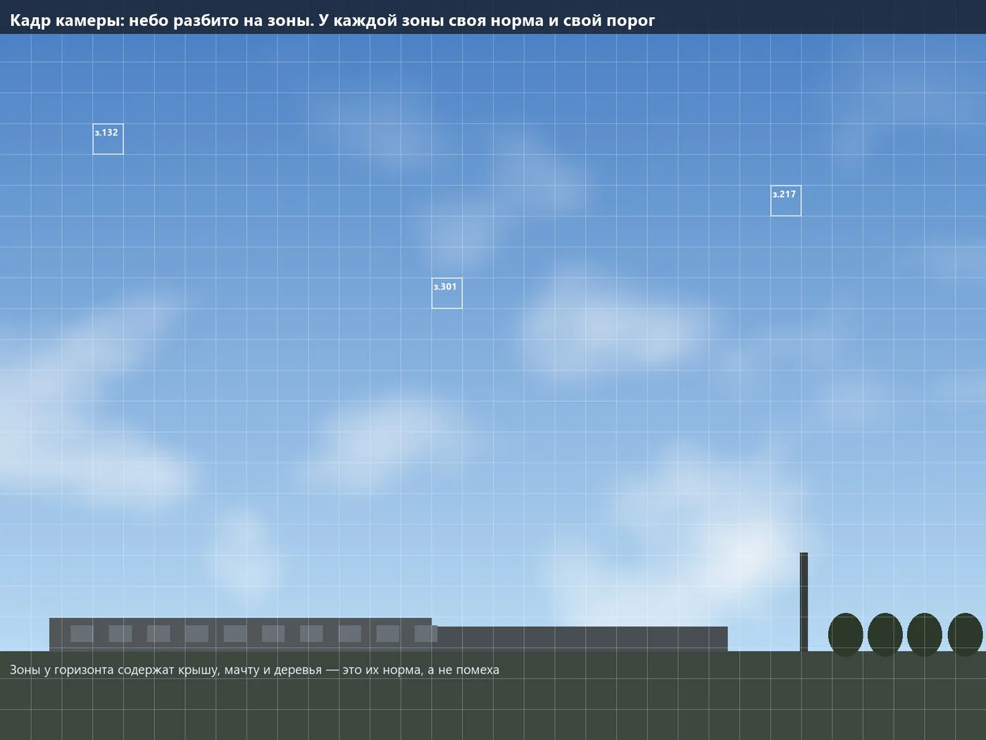
The sky appears uniform, with haze on the horizon, a blue expanse overhead, clouds, sunlight, the edge of the roof, and the mast. However, the overall system struggles to process all of this information simultaneously, leading to errors at the edges of the frame. The zone above the roof always recognizes the edge of the roof, while the zone in the center only sees the sky and clouds, making it the most sensitive to errors.
The roof, mast, trees, and wires at the edge of the frame no longer constitute an obstruction; they are part of the normal environment.
At the horizon, where there are branches and haze, the sensitivity is higher; at the zenith, where the sky is clear, the sensitivity is maximum.
A working zone is a pre-defined area: the azimuth and angle of view, calculated once during installation.
The number of zones is known in advance – there are no situations where a detector finds "four hundred objects and everything is resolved."
A new source of false alarms appears in one zone – one zone is recalibrated, while the others remain unchanged.
The operator can see which zone triggered and what was detected within it. This is more important for security personnel than a single general response.
03 Why a point in the sky is already a detection
Detection relies on contrast, not shape. There are no bushes, cars, or shadows in the sky: within the zone, the brightness changes by a few levels, and the pattern repeats from frame to frame. Any dark spot on this background is statistically detectable, even if it cannot be seen with the naked eye.
| What is happening | Size |
|---|---|
| Brightness of the sky in the zone | Approximately 180 levels out of 255 |
| Noise level of the sensor at this brightness | 2–3 levels |
| The drone covers a quarter of the pixel area | The pixel darkens by approximately 30 levels |
| Signal-to-noise ratio | Approximately ten |
A tenfold increase above the noise level is a clear signal. Even an object smaller than a pixel will be darkened proportionally to its covered area, so the detection limit is further than the "four pixels per target" standard, which is designed for camouflaged targets on a patterned background. For a dark object against a clear sky, reliable detection begins with two pixels, and a stable track appears with three or four. To distinguish a quadcopter from a bird in an image, 15-20 pixels are needed – but this task is solved by the behavior of the object.
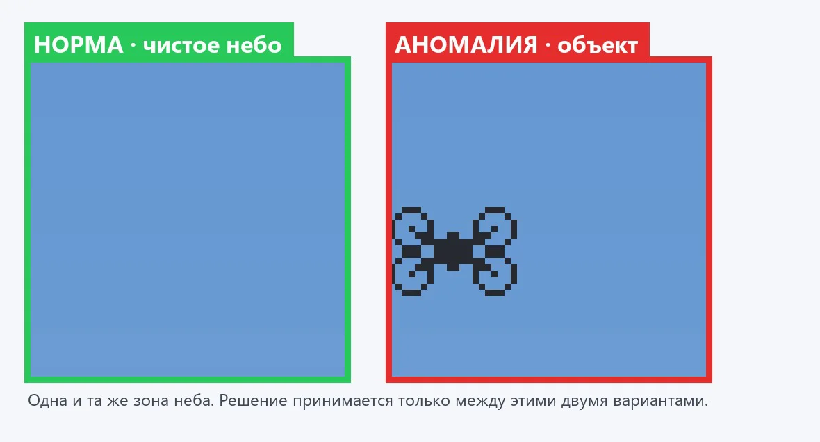
A single, isolated noise trigger might activate in a single frame, but it won't repeat in the same area, and certainly won't shift to an adjacent area in the correct direction. The requirement of "confirming the object over three or four consecutive frames with consistent movement" virtually eliminates false triggers and only takes a fraction of a second.
04Detection Range: Calculation
The range is determined by the angular size of the pixel: pixels on the target = target size × focal length ÷ (pixel size × range). This calculation is for a 20-megapixel camera with a 2.4 μm pixel size and a 1-inch sensor; the target is a quadcopter with a rotor diameter of 0.4 meters.
| Lens | Field of view | 128 px zone | Detection, 2 px | Confidently, 4 px | Recognition, 16 px |
|---|---|---|---|---|---|
| 25 mm | 29,4° × 19,9° | 0,70° | 2,100 m | 1,040 m | 260 m |
| 35 mm | 21,3° × 14,3° | 0,50° | 2,900 m | 1,460 m | 365 m |
| 50 mm | 15,0° × 10,0° | 0,35° | 4,200 m | 2,080 m | 520 m |
| 75 mm | 10,0° × 6,7° | 0,23° | 6,250 m | 3,120 m | 780 m |
| 100 mm | 7,5° × 5,0° | 0,18° | 8,300 m | 4,170 m | 1,040 m |
For larger targets, the range increases proportionally: a 1.2 m wingspan aircraft with a 50 mm lens can reliably detect targets at six kilometers. However, at approximately two kilometers, the limiting factor is not the camera, but the air – haze reduces contrast.
| Meteorological visibility | Contrast at 1 km | At 2 km | At 3 km |
|---|---|---|---|
| 30 km, clear | 88 % | 77 % | 68 % |
| 20 km, normal day | 82 % | 68 % | 56 % |
| 10 km, light haze | 68 % | 46 % | 31 % |
| 4 km, fog | 38 % | 14 % | 5 % |
There's no point in using lenses longer than 75mm for range: in normal weather conditions, the air will only allow visibility up to 2-3 kilometers. A reasonable working range is from 300m to 2km, which is exactly what a warehouse needs. The drone travels at a speed of 20 m/s: detection at 1,500m gives 75 seconds – enough time to evacuate people from the loading zone, stop unloading, close the gates, and call security; at 700m, it's 35 seconds, which is sufficient for people and the alarm signal.
05 Camera, optics, and thermal imaging device
| Requirement | Meaning | Why |
|---|---|---|
| Resolution | 20 MP, 5472 × 3648 | The smaller the pixel angle, the further the point can be seen |
| Pixel size | 2.4 μm | A pixel twice smaller – twice further detection |
| Sensor | 1 inch | With a small pixel, it maintains a wide field of view |
| Type | Monochrome | Color sensor loses half its resolution on a small, dark spot |
| Shutter | Global or slow rolling | A distant object appears to move slowly |
| Interface | GigE, up to 6 frames/s at 20 MP | Approximately 960 Mbit/s – this speed is sufficient for the sky |
| Mount | C-mount | Any standard industrial optics |
All the figures were calculated for the standard industrial camera, the HIKROBOT MV-CS200-10GM (monochrome) model, which is currently available, has a predictable price, and the software already supports direct operation with it. The lens has a minimum size of 1 inch, a resolution of 2.4 μm per pixel, an F2.8 aperture, and a fixed focal length without zoom, with focus and aperture adjustment via screws (the camera is placed outdoors and vibrates). Kowa, Computar, Fujinon, and Hikrobot optics are suitable. For circular surveillance, the optimal focal length is 25 mm: twelve cameras cover 360° with overlap, and reliable detection can be achieved up to 1 kilometer.
Thermal imaging camera: 24-hour operation
To use in the dark, at dusk, or when working against the sun, a thermal imager is added – not a separate system, but another channel of the same method: the same grid of zones, its own "normal/anomaly" for each zone, and the same tracking. The night sky in the infrared range is cold and uniform, while the drone's motors, battery, and regulators appear as a warm spot against the cold background.
| Parameter | Meaning |
|---|---|
| Sensor | Uncooled, 640 × 512, 12 μm pixel |
| Lens | 50 mm, field of view approximately 9° × 7° |
| Drone detection: 0.4 m, 2 pixels | approximately 830 m |
| Confidently, 4 px | approximately 420 m |
| Mode | Around the clock, at dusk, when the sun is setting, or in a hazy atmosphere. |
Zones for two channels are linked to the same celestial coordinates: during the day, they confirm each other – an object found in both channels is almost certainly real – and at night, the track is followed by the thermal imager. The operator sees a single track, a single screen, and a single log.
06 Transition between zones: track
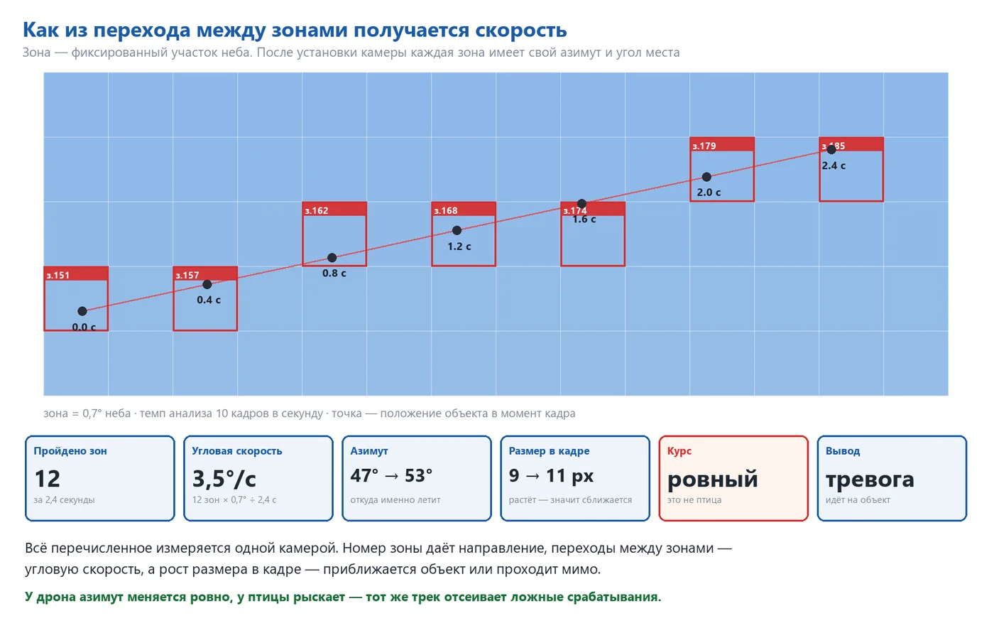
A single zone activation is not an event in itself. It becomes an event when the object moves from one zone to another. After installation, each zone receives constant coordinates in the sky – azimuth and altitude – and the number of the activated zone becomes the direction in degrees.
| Size | Source | Accuracy |
|---|---|---|
| Direction to the object | Coordinates of the activated zone | A half-zone approach, with further refinement within the zone, is preferable. |
| Angular speed | Number of zones traversed ÷ time | Limited only by the shooting speed |
| Course | How the azimuth changes from frame to frame | It's immediately clear whether the object is moving in a straight line or meandering |
| Zooming in | Does the size of the object in the frame increase? | Confidently tracked over a long section of the track |
The area is 0.7 degrees of the sky. The object passes through twelve zones in 2.4 seconds – an angular speed of 3.5 degrees/second. The bird's movement is erratic and close-range, while the aircraft's movement at altitude is small and constant. The drone following the object has a smoothly increasing movement. A frame rate of six to ten frames per second provides three to five measurements per zone – the track is smooth. The adjacent cameras have overlapping fields of view, and when an object leaves the frame of one camera, the next camera captures it as the same track.
07 Approaching or passing by
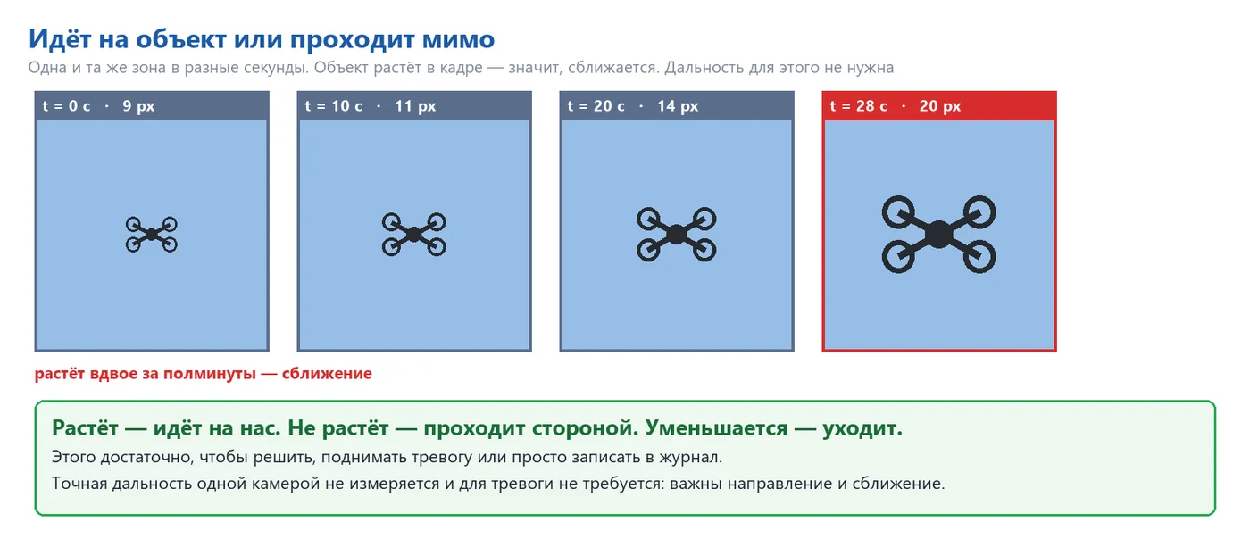
The key factor is not the distance, but the change in the object's size within the frame. If the object's size increases, it's moving towards us; if it remains steady while the bearing remains constant, it's passing by; and if the object's size decreases, it's moving away. These three states correspond to three reactions: alarm, observation, and logging. It's impossible to obtain an accurate distance measurement with a single camera, and in the case of alarm, this measurement is not necessary: the combination of "unidentified object, constant bearing, approaching" is sufficient.
08 Bird or Drone
False alarms caused by birds are the main practical problem of optical observation of the sky. This is solved by analyzing behavior, rather than simply looking at the image.
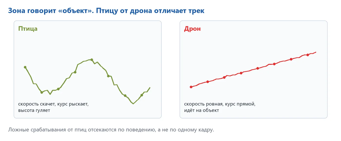
| Feature | Bird | Drone |
|---|---|---|
| Course | wanders, frequently changes | smooth, consistent |
| Angular speed | jumps, with pauses and hovering | smooth, monotonously changes |
| Height | moves up and down | maintained |
| Trajectory | random, usually along | often directly on the object or around it |
| Group behavior | often a flock, with many markings | a single marking |
Each zone's model is trained on synthetic data: real images of the sky in that specific area are artificially modified by adding objects of varying size, position, rotation, and contrast. This creates conditions that a pilot might not experience for months, such as low sun in the morning and evening, twilight, haze, and cloud cover, noise, blur, mast vibration, and glare. The same type of interference is applied to both normal and anomalous data, so the evening sky does not trigger false alarms. The basis of the training is the real sky of the object; after the pilot, real flight paths are added.
A crow at fifty meters provides a large, clear target, and the detector would appear more convincing than a drone from a kilometer away. However, the track allows for filtering in just two seconds. Each zone maintains its own statistics of false alarms: if birds fly over the roof corner every morning, the threshold for that zone is automatically raised.
09 Performance
The 20MP frame contains 1,176 128-pixel zones. It is not necessary to send all of these to the neural network every frame – the work is divided into three stages, and a heavy neural network only works when there is something to see.
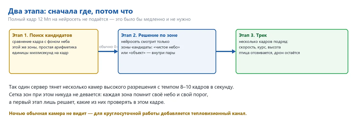
| Stage | What it does | Price |
|---|---|---|
| 1. Candidate search | comparing the frame with the accumulated sky model for each zone on the graphics card | 1–2 ms per frame |
| 2. Decision per zone | The neural network only analyzes candidate zones, typically ranging from zero to five on the frame. | 3–5 ms per zone (RTX 50 series) |
| 3. Tracking | Matching markers between frames, course, speed, proximity | Microseconds |
A single NVIDIA RTX 50-series graphics card can handle up to twelve cameras with some headroom. The limitation is the network: 20 megapixels at six frames per second – approximately 960 Mbps per camera, meaning a gigabit port per camera and a ten-gigabit connection to the server for every six cameras. Processing the entire sky visible from all twelve cameras using a neural network takes 42-71 seconds per cycle. With candidate searching, the panoramic view is updated several times per second, and each zone still remembers its own sky, normal map, and threshold.
10 System components and coverage
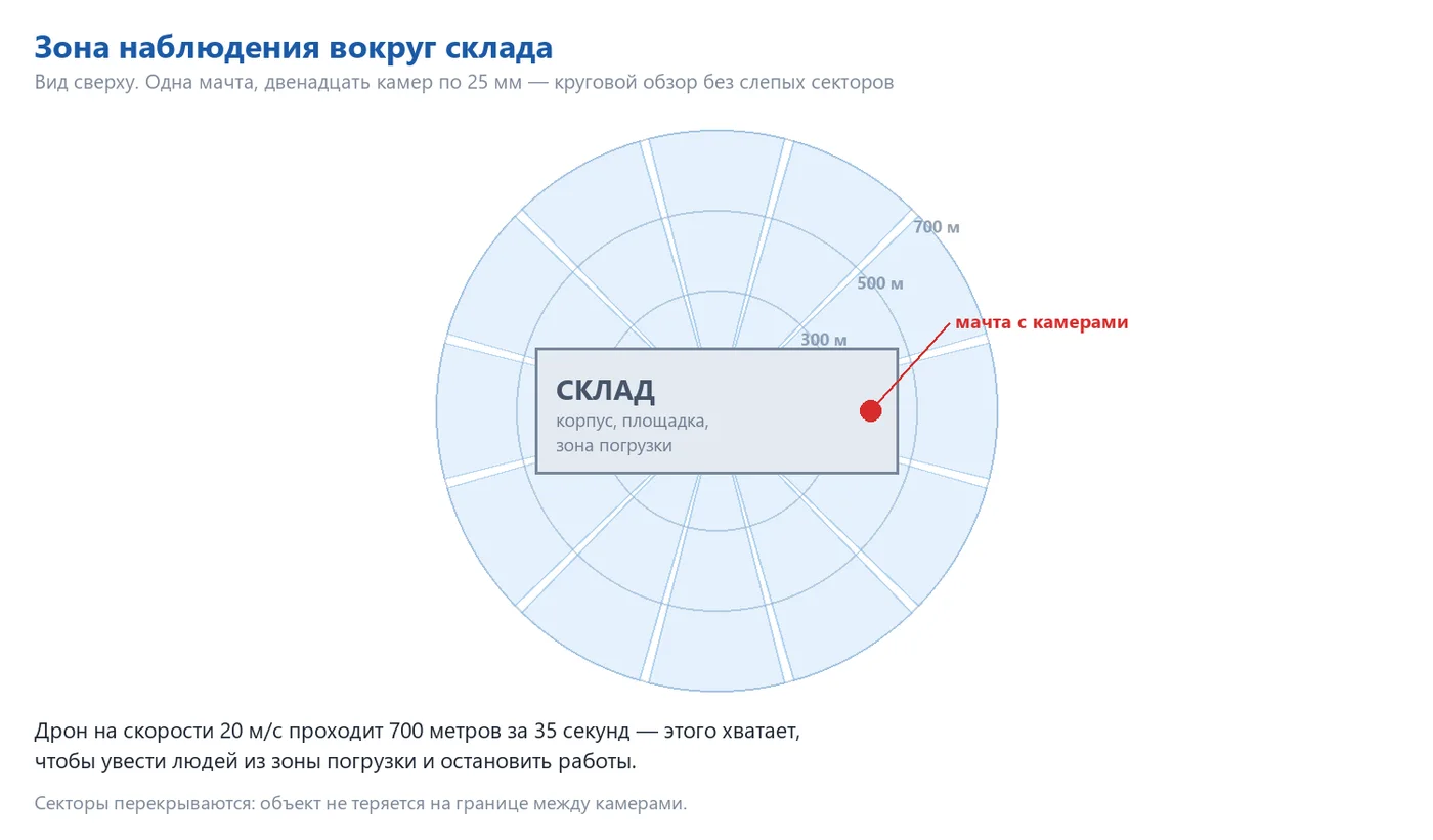
| Option | Cameras | What it covers |
|---|---|---|
| Pilot | 1 camera, 50mm | One sector of 15°, detection up to 2 km; verification of the method on real-world objects |
| Direction | 3–4 cameras, 35mm | Sector 60–85°, loading bay and loading zone side |
| Circular | 12 cameras, 25mm | 360° coverage with overlap, detection up to 1 km |
| Reinforced circular | 12 × 25mm + 4 × 75mm | Circular surveillance plus long-range access on main routes |
| 24 hours | Any option + 640 × 512 thermal cameras | Night, twilight, and sunny conditions; same zone grid and same track |
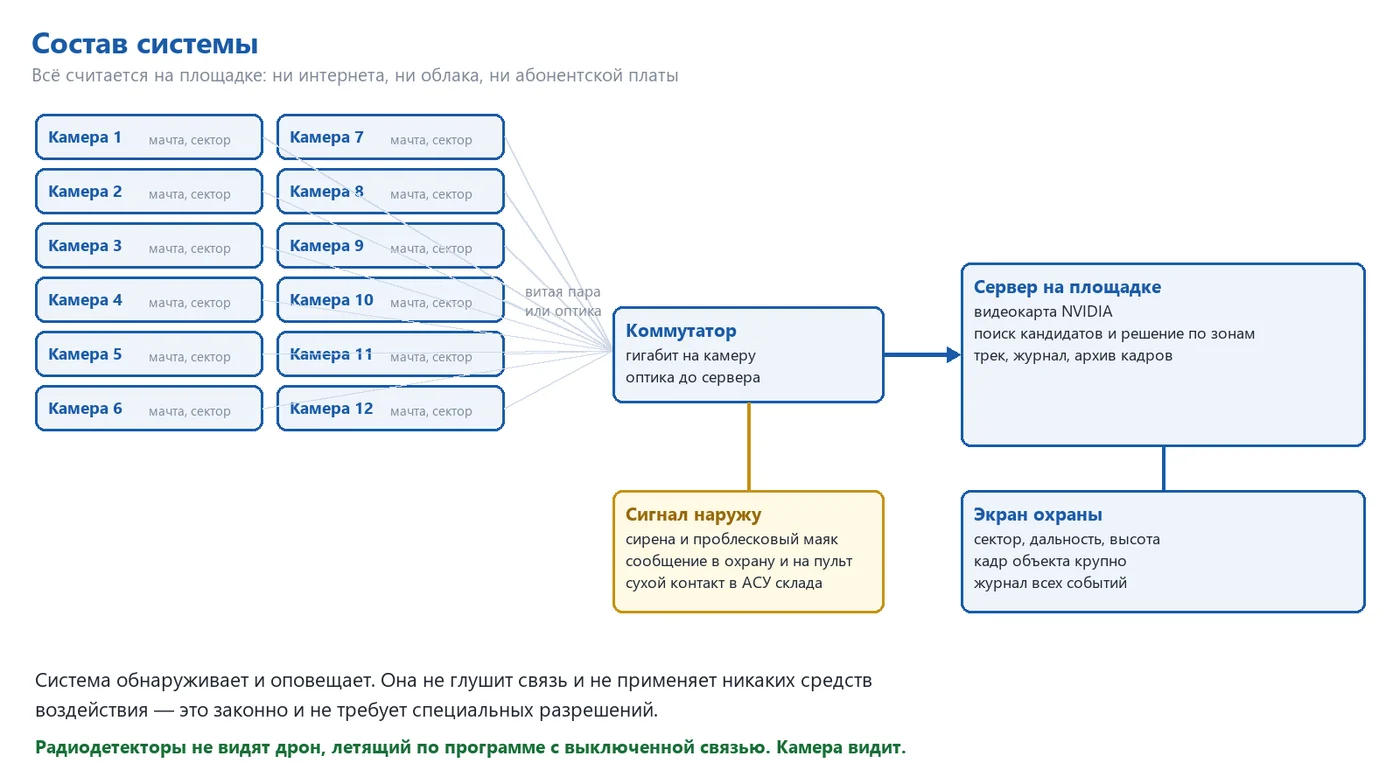
The system is modular: the minimum setup includes one camera covering a specific area, which immediately triggers an alarm. External outputs include: a security monitor displaying (sector, azimuth, angle of view, track, object frame), a siren, and a beacon in the loading zone, a dry contact connection to the warehouse automation system (to stop loading and close the gates), and a message sent to the existing security system, along with a log file containing archived footage – providing evidence for insurance and law enforcement agencies.
11 Robot and Stereo Camera: Precise Tracking
Overhead cameras answer the question "where." The next step is "what is it and how fast is it moving": an industrial robot, BORUNTE, with a stereo head – two cameras with long-focus optics mounted on a rigid arm, is added to the system.
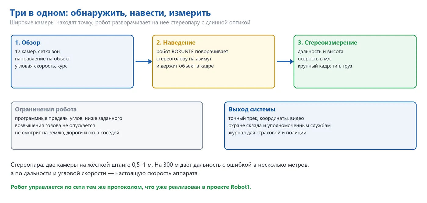
The zone on the overview camera is activated, indicating the azimuth and elevation angle.
The network server rotates the stereoscopic head of the robot in this direction (the protocol is already implemented in Robot1).
In a narrow field of view, the object occupies dozens of pixels: the type of device and the load underneath are visible.
The distance is determined by the difference between the two cameras, and the angular speed and elevation angle provide speed in meters per second and height, respectively.
The robot keeps the object within the allowed angles.
| Stereo pair base | Distance | Distance error |
|---|---|---|
| 0.5 m | 150 m | Approximately 1 m |
| 1 m | 300 meters | approximately 2 meters |
| 1 m | 600 meters | approximately 9 meters |
The error increases quadratically with distance, so the stereo pair is a tool for close-range use, up to a few hundred meters, while the wider view remains within the defined zones. The robot has programmed limits for each axis: the head cannot be lowered below the specified angle or turned towards residential areas, roads, and neighboring properties.
Sound channel
The drone's propellers produce a consistent hum of 150–400 Hz with clear harmonics, which birds do not produce. The sound confirms that the object in the sky is the drone: a directional microphone on a stereo head listens in the same direction as the cameras, and the microphone grid on the mast (6–8 microphones) independently determines the direction to the source and can turn the robot, even if the optics haven't yet detected the object.
| Conditions | Sound range | Direction accuracy |
|---|---|---|
| Quiet night, empty area | 300–500 meters | 2–3° |
| Typical day | 150–300 meters | 3–5° |
| Loading, trucks, ventilation | 50–150 m | 5–10° |
Option: pneumatic net
A pneumatic net launcher can be installed on the robot: using compressed air, without gunpowder or projectiles, it throws a net that entangles the propellers; the version with a parachute slowly lowers the captured drone. The range is typically 20–100 meters, and targeting is based on stereo vision data. Deployment is only initiated upon confirmation from the operator.
Intercepting a drone, even with a network, constitutes interference with an aircraft's flight. The right to such actions is reserved for authorized agencies, and commercial storage facilities do not have this right by default. Therefore, the interception module is an option for those who have the authority, and it only functions with human confirmation. Detection, tracking, and measurement are legal everywhere and function without it.
12 What the system does and what it doesn't do
Does
- detects foreign objects in the air above and around the object;
- displays direction, course, and angular speed, and answers the question "is it approaching us or passing by";
- differentiates a drone from a bird based on behavior;
- triggers an alarm dozens of seconds before approaching;
- maintains a log of images and tracks for each event;
- operates autonomously on site, without internet or subscription fees.
Does not
- does not interfere with the drone in the standard configuration – it does not jam or disable; network interception is a separate option with human confirmation;
- A standard camera cannot see at night, so the thermal imager uses the same grid of zones;
- It cannot see through fog and heavy snow, and in fog, the range decreases, and the system indicates a reduction in visibility;
- It does not replace a radio detector, but complements it: the radio detects the drone when it is in communication, while the camera does not.
13 Implementation Procedure
| Stage | Contents |
|---|---|
| 1. Site Assessment | On-site inspection, selection of mast and directions, assessment of sky conditions and light pollution, and sector agreement. |
| 2. Pilot | One camera on the main direction, two weeks of operation in real-world conditions at the site. |
| 3. Data Collection and Training | Recording the sky in all conditions – clear, cloudy, haze, sunrise, sunset; training models by zone. |
| 4. Threshold Setting | Test flights by the customer's drone at different ranges and altitudes, and threshold selection by zone. |
| 5. Acceptance | A series of test runs, measuring the probability of detection at different distances and the number of false alarms per day. |
| 6. Deployment | Remaining sectors, transmitting signals to the security and automation systems of the warehouse. |
| 7. Support | Monitoring for the first few weeks, and retraining based on accumulated false alarms. |
During the inspection, everything is measured, not just declared: a control drone flies according to a pre-defined program, the system generates a log, and the log is compared to the flight program. The longest part is not the assembly, but the sky: the model needs to see a clear sky, clouds, haze, low sun, and rain – some of these conditions depend on the weather. Therefore, the pilot uses one camera and starts early, working in parallel with the assembly of the other parts.
Also read: engiAI – Machine vision and the ZONE-PAIR method · engiAI engiAI manual (PDF) · Robot1 – Robot control.