Robot BORUNTE BRTIRUS0707A
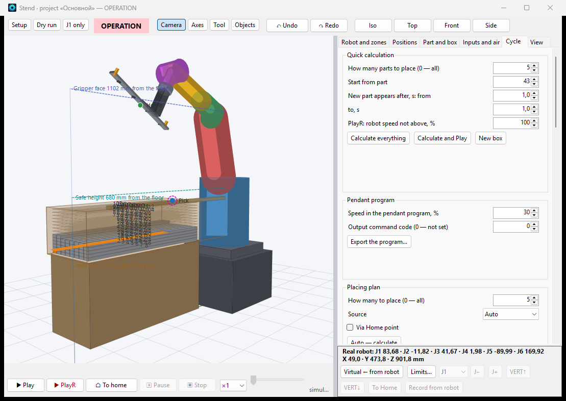
We've combined two things that typically exist in separate worlds: machine vision system engiAI featuring its own neural network training pipeline and a six-axis industrial robot BORUNTE BRTIRUS0707AThe result is a robot that doesn't simply execute a pre-programmed sequence, but.. It identifies a detail and adapts to it in real time.
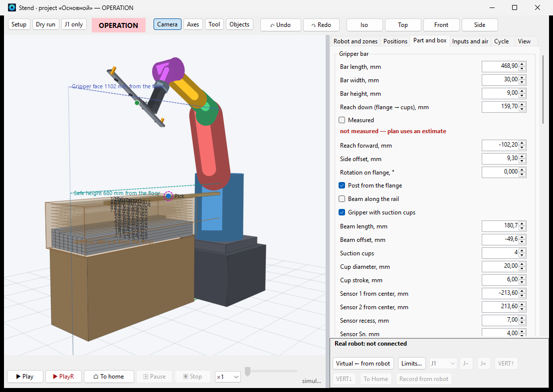
The test scenario that demonstrated the system's capabilities: a box is placed on a table in a random orientation, and the operator rotates it freely – from 0 to 360 degrees. A camera positioned above the box captures the image, a neural network determines the angle of rotation with an accuracy of one degree, and the robot arm replicates the box's position – precisely orienting its gripper underneath it. There are no supports, cradles, or position sensors; only a camera, a neural network, and a robot.
What the system consists of
engiAI – Computer Vision. It provides a complete AI workflow: connecting industrial cameras (SICK, Hikrobot, GigE Vision, USB), defining inspection zones directly on the live video feed, generating training datasets from a few frames, training YOLO models on GPUs (using CUDA), and performing real-time inference at the camera's frame rate. The OUTPUT module converts the recognition results into actions, such as sending TCP packets to robots or PLCs, and controlling the camera's discrete outputs.
Robot1 – Robot control. Direct communication with the HC1 controller using the open JSON/TCP protocol, without a teach pendant or proprietary software: manual control of each axis, saved positions, a 3D model of the robot with a base of positions. The key feature is TCP receiver for commands from the AI: a rule for each axis with the command name, speed, offset, inversion, and angle adjustment to the nearest path (±180°).
The connection between the programs is standard TCP/IP. This is fundamental: any device that can open a socket can be integrated into the chain – PLCs, other robots, SCADA systems, ERP systems, etc.
How it works: from frame to movement
- Frame. The camera displays an image of the inspection area (in our demonstration setup, SICK, 2048x2048 matrix).
- Excellent. The YOLO model classifies the position of the part: each degree of rotation represents a separate class (0…359 for a full circle or 0…180 for symmetrical parts).
- Package. The OUTPUT rule defines a command – for example, "J6 315" – and sends it over TCP. The rule is created once for the entire model: the substitution {class} automatically transmits the name of the recognized class.
- Axis control rule. Robot1 applies axis settings – inversion, offset, and near-field path – and commands the controller to set the target angle at a specified speed.
- Movement. The axis rotates – the gripper aligns perfectly with the part.
The delay from rotating the box to starting the axis — about a second, and it is controlled: all delays are specified in the settings.
Training without a dataset and without an ML engineer
A common challenge in machine learning for manufacturing is the need to collect and label thousands of images. In engiAI, this is addressed by generating synthetic data: the operator takes one photo of a part in the area, and the program automatically creates a training dataset.
- rotates the window area across the entire frame by a specified increment (e.g., 0.1°), resulting in a true background being captured, with the detail not being cropped by the frame: the image is automatically expanded to a square along the diagonal of the area;
- adds variations in brightness and contrast within specified limits and mirrored copies;
- automatically sorts frames into classes (0…359) and divides the sample into train and val.
From a single image, hundreds of training files can be generated. Next, the "TRAIN AI MODEL" button is pressed, and after a period, the model is ready for use. The entire cycle of "showing the detail → training → robot works" is performed by the line operator, not a hired ML engineer.
The data stream should not interfere with the robot's operation.
The neural network processes recognition tasks dozens of times per second, and it is not possible to directly transmit these results to the actuators – the actuators fail due to the overwhelming number of commands. A multi-stage protection system, tested on a live robot, is implemented:
- Dead Zone – the movement between adjacent classes (315↔312) does not affect the axis at all;
- Stability Requirement – the new class must remain stable for a specified period: the neural network should not cause the axis to move towards distant destinations;
- Smooth Transition – if the target has changed while the robot is moving, the robot will not reach the outdated point: controlled braking, clearing the controller queue, and immediately moving to the new target. Intermediate commands are discarded – only the current target is relevant.
- Pause between movements – a strict limit on the frequency of commands sent to the controller;
- Automatic Recovery – In the event of an error, the controller's queue is automatically cleared, and the target is reset; both programs maintain continuous file logs.
How is this better than a traditional industrial robot?
A traditional industrial robot repeats a rigidly programmed trajectory. All that the robot "knows" about the part is provided by the mechanics around it. This is the main source of costs and limitations in automation. AI vision eliminates these issues one by one.
Cost and Time
- No mechanical positioning fixtures are required – such as workbenches, supports, vibration bunkers, and centering stations. The part can be positioned in any way; the robot will automatically adjust to it. A fixture for a single part often costs as much as the robot itself – and in this case, there is no fixture at all.
- The changeover is from a new product – watches – not weeks. The camera details were shown, the model was trained, and the rule was set – the line is working. No need for an integrator's visit or a production shutdown.
- Smaller production runs become profitable. Traditional automation only pays off with large print runs. Even a single-day run can be profitably automated when setup costs are minimal.
- One tool instead of three systems: The robot's guidance, quality control, and rejection functions operate within a single program using a single camera.
Flexibility and Quality
- Tolerance to the real world. The conveyor belt has shifted, the part is lying crookedly, a new batch has arrived with a different shade – the standard cell is working, and the AI cell continues to function: it looks at the part, not the coordinates.
- Quality control is free. The same model used to identify defects, such as a crumpled box, a torn label, or incorrect assembly, uses the same set of rules to identify and reject the item.
- Any axis – controlled by AI. The rules are set independently for each of the six axes: today, a single gripper rotation is used, and tomorrow, full positioning is achieved using multiple axes simultaneously.
- Continuous feedback. The robot is not a "blind executor": every movement is a response to what is actually visible in the frame, with a record of all decisions.
Openness and Scalability
- Independence from the robot's brand. The connection uses an open TCP/IP protocol: currently, it uses BORUNTE, but the same protocol can be used to control another manipulator, a rotary table, or a PLC in the future.
- On-site retraining. The model is not a "patch": if a new detail or defect appears, it can be retrained in a matter of hours, directly on the production line, using real-time images and actual lighting conditions from the factory.
- Cell replication refers to the copying of software and the model file, rather than a re-design of the integration.
- Transparency. Both programs have persistent logs and a database log of events: the entire history, from individual frames to axis movements, is visible. This provides the basis for statistics, quality metrics for batches, and predictive maintenance.
Where is this applicable?
- Packaging and Logistics: Box orientation before stacking, palletizing and de-palletizing mixed pallets, conveyor-based picking of items lying randomly.
- Quality control with rejection: One camera both inspects and controls the execution mechanisms.
- Machine loading (CNC, presses): raw materials in bulk or on pallets, without vibration bunkers.
- Assembly: Positioning of parts, and verification of correct installation at each stage.
- Food production and agriculture: These are variable sectors where mechanical standardization is fundamentally impossible.
- Processing and Sorting: The area of "non-catalogued" items represents a challenge where traditional automation is ineffective.
What's next?
- Stages and external triggers: A program consisting of steps (coordinates for all axes and speed at each step), adding and removing stages from the interface, starting stages based on TCP signals from vision, PLC, or operator;
- Gripper in full posture: from one axis to the position and orientation of the part along multiple axes simultaneously;
- Multi-chamber cells and synchronization of multiple robots;
- Online self-learning: the system automatically collects complex examples and presents them in a new training dataset.
Technology Stack
.NET 9 (WinForms) · YOLO classification, ONNX, CUDA · SICK / Hikrobot / GigE Vision / DirectShow cameras · BORUNTE BRTIRUS0707A robot (HC1 controller, open JSON/TCP protocol) · SQLite · TCP/IP integration with any equipment.
The project demonstrates the key point: the barrier to entry for "lazy" robotics has fallen. No need for a team of ML engineers and months of integration – just a single image of a component, a training button, and an open protocol. The robot ceases to be the most expensive and inflexible machine in the workshop – and becomes a versatile tool that can be retrained in a matter of hours.