Remote support: a turnkey robot with machine vision in any country
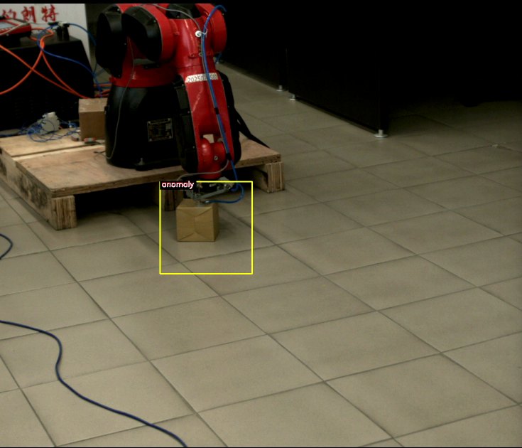
The camera and neural network inform the robot about the presence of a part, its type, and its orientation. No guides or fixtures are needed for precise placement of the part.
Each response from the neural network triggers a specific robot sequence: placement, sorting, rejection, or waiting.
A single camera identifies and inspects the products. A stereo pair of cameras or a single stereo module measures the height and dimensions.
Configuration, startup, training, and support are all handled remotely. Only your engineer is needed on-site.
Dear Managers and Specialists!
"Vector Technologies," based in Minsk (Belarus), has been working in industrial automation for 17 years, since 2009. We have developed our own software for robots with machine vision and offer to implement it in your production facility in any country, without the need for our engineers to travel.
The work that is typically performed by an on-site integrator, we perform remotely via the internet. We analyze the task using video, create equipment specifications, remotely configure software, train the neural network using your products, oversee the robot's deployment alongside your engineers, and provide online training for your staff. You don't incur travel expenses, and project timelines are not affected by visa requirements or flights.
The machine vision and robot control programs were developed in our company. Therefore, we are responsible for the entire process, from the camera image to the robot's movements, and we can customize the programs to meet your specific needs.
What you get
The robot performs repetitive tasks in each shift: it picks up, orients, places, and sorts products.
The same camera that guides the robot also inspects each product and sends defective items to the rejection area.
A new product requires a new neural network model and new routines, rather than new mechanical fixtures.
A single team, which developed the software itself, handles the programming, configuration, and deployment.
Sincerely,
Sergey Kuntsevich
Technical specialist at "Vector Technologies," software engineer, software developer engiAI and Robot1
+375 33 380-78-10 (Viber, WhatsApp, Telegram) · support@engi.live
01A robot that can see
A standard industrial robot simply repeats a pre-programmed trajectory. It doesn't know if a part is in place, what type of part it is, or how it is oriented.
Therefore, mechanical fixtures are built around the classic robot: supports, jigs, vibratory feeders, and centering stations. The fixtures for a single product often cost as much as the robot itself, and switching to a different product requires modifying the fixtures. This approach makes it uneconomical to automate small production runs.
A robot with machine vision first "sees" and then acts. The camera captures an image of the product, a neural network analyzes the image and provides information, and based on this information, the robot chooses its action.
| What the camera determines | What the robot does |
|---|---|
| The presence or absence of a part in the gripper zone. | The robot starts a cycle when a part is detected and waits until the zone is empty. |
| Product type: model, color, size, or variant. | The robot executes a pre-programmed sequence specifically for that product type. |
| The product can be rotated from 0 to 359 degrees in 1-degree increments. | The robot rotates the gripper to the correct orientation for the product, eliminating the need for orientation guides. |
| Defect: chip, component misalignment, missing element, foreign object. | The robot places the product in the reject bin, and the event is recorded in the log. |
| The height, length, and width of the box are measured using a stereo camera. | The robot descends precisely to the surface and does not press on the cardboard. |
02How the system works
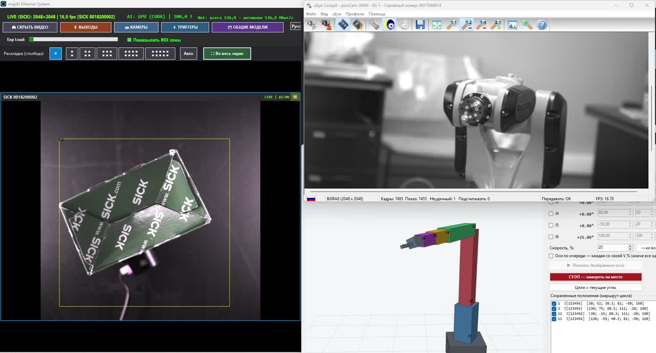
The system consists of two programs developed by us: engiAI handles the vision processing, and Robot1 controls the robot. The programs can run on the same computer or on separate computers and communicate with each other over a standard network.
The camera continuously captures images of the product or triggers based on a sensor signal.
The neural network provides information for each area of the image: normal, defective, product type, or angle.
The command sends a signal over the TCP/IP network or activates the camera's output.
The program receives the command and selects the robot's path.
The robot executes the path, activates the gripper, and sends signals to the equipment.
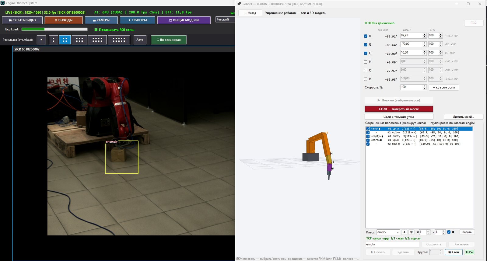
The data from the camera can be received not only by the robot. It can also be accessed by a PLC controller, a rotary table, another manipulator, or a SCADA system, provided the device is capable of establishing a network connection.
The neural network performs calculations on a computer located at the production line. The images are not sent to the internet, and the system's operation is not dependent on cloud services.
The neural network responds dozens of times per second. Robot1 only accepts a new target after confirming stability and ignores minor fluctuations in the response, which prevents the robot's actuators from malfunctioning.
The time from a change in the part's position to the start of axis movement is approximately 1 second. All delays are configured in the settings.
03One robot performs multiple tasks
In the Robot1 program, each neural network output corresponds to a specific robot movement sequence. This sequence defines the robot's posture, speed, and the number of repetitions.
When the camera reports "normal," the robot executes the route for a good product. When the camera reports "defect," the robot executes the route to the reject bin. Repeating the same command during movement does not disrupt the robot, and for critical routes, interruption can be disabled.
| Neural network response | Robot route | Example on our test bench |
|---|---|---|
| "normal" | The robot picks up a good product and moves it to the loading station. | The path for a good product consists of two positions. |
| "defect" | The robot moves the product to the rejection area. | The path for a defective product consists of two positions. |
| "empty" | The robot returns to the waiting position and waits for the next product. | One waiting position. |
| Angle: 0–359° | The robot rotates the gripper to match the angle of the product. | The J6 axis rotates to follow the box. |
What operations does the robot combine in a single cell?
The robot arranges products in boxes in rows and layers. The software automatically calculates the position of each item.
The robot sorts products by type, size, or grade based on the output of a neural network.
The robot rotates the product to the angle determined by the camera.
The camera, which guides the robot, simultaneously checks the product for defects.
The robot loads machines, presses, or conveyors based on signals from sensors and inputs.
The robot removes defective products from the production line and places them in a separate container.
For a new product, a new neural network model and a new set of paths are created. Everything related to a specific product is stored in the project file. Switching to a different product is done by selecting the appropriate project and model set, without requiring any reprogramming of the robot or new tooling.
04Remote setup and support available in any country
Our programs are designed so that the system can be prepared, tested, and launched without an on-site integration engineer. We work from Minsk with clients in any country and time zone, following a pre-arranged schedule.
He is preparing the project, configuring the programs, and training the neural network.
Remote access to the cell's computer and video conferencing with your engineer are available.
Computers, cameras, and robots for your manufacturing facility, anywhere in the world.
He is stationed near the robot, monitoring its movements and keeping the emergency stop button within reach.
Why remote deployment is reliable
We assemble the robot's cell in a three-dimensional model using the Stend software. Reachability, layout planning, and cycle time are verified before the first movement of the actual robot.
The neural network model is trained on images of your products. These images can be sent as files or captured during a remote connection.
The poses, routes, entry and exit rules, camera settings, and models are stored in files. We prepare the project internally and then pass it on to you.
Both programs record every action. Through the logs, we can see what happened at the workstation without having to physically visit the site.
The operator works in the program in their own language. The program manuals are also available in 14 languages.
The engiAI and Robot1 programs can be downloaded from the engi.live website and tested immediately: they work for 20 minutes without a license.
How remote implementation works
| Stage | What we do remotely | What you do on-site |
|---|---|---|
| Task breakdown | We conduct a video conference, review photos and videos of the area, and propose a cell layout. | You send us videos of the operation, along with the dimensions and weight of the products. |
| Specifications | We create a list of equipment: robot, camera, lens, lighting, computer with a graphics card, gripper, sensors. | You purchase the equipment from local suppliers according to our specifications. |
| Cell design | We assemble the cell in a digital twin environment, calculating routes, reach, and cycle time. | You provide us with the dimensions of the installation location and photos of the area. |
| Assembly | We provide guidance via video conferencing and provide connection diagrams for cameras, sensors, and outputs. | Your mechanic and electrician install the equipment. |
| Vision system | We connect to the cell's computer, configure the camera, define zones, and train the neural network using your products. | You place the products under the camera as requested. |
| Robot startup | We guide the startup process step-by-step: a dry run, movement of a single axis at low speed, followed by a full cycle at a limited speed. | Your engineer is located near the robot, next to the emergency stop button. |
| Training | We conduct online training sessions for operators, technicians, and process engineers, and we provide recordings of the sessions. | Employees learn using their own workstations. |
| Support | We refine the models, add new routes, analyze logs, and improve programs. | You inform us about a new product or a new task. |
The robot is always deployed in the presence of a human operator on site. We configure the system and monitor the process remotely via video conferencing, while your engineer controls the robot's movements and has access to the emergency stop button. During the initial deployments, the robot's speed is limited by the software.
Remote training on our programs
The engiAI program: Machine vision
- Connecting and configuring industrial cameras.
- Defining control zones on live images.
- Collecting images and synthetic data for training.
- Training the neural network and verifying the results.
- Control signals: commands to the robot and the PLC controller, discrete outputs, sound.
- Operation based on sensor signals and encoder data from the conveyor.
The Robot1 program: robot control
- Robot connection, manual axis control, and position saving.
- Paths and cycles, stacking in boxes in rows and layers.
- Input and output rules, pneumatic gripping, and sensor-based safety features.
- Receiving commands from the vision system.
- Digital twin of Stend and a secure transition to a real robot.
- Downloading the cycle program to the robot's teach pendant.
For remote operation, you need a stable internet connection on the cell's computer, remote access software approved by your IT department, and video conferencing capabilities from a smartphone or laptop connected to the robot.
05 Single-camera vision: engiAI
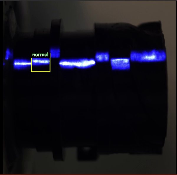
engiAI is a machine vision software program that utilizes a neural network. Within a single program, the operator connects cameras, defines control zones, trains the neural network, inspects products, and manages rejection processes.
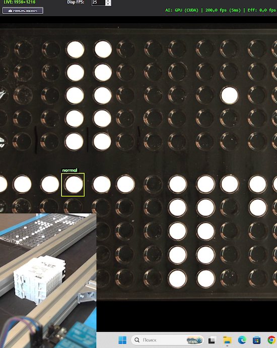
The program checks for the presence of the part and verifies that all components are in place.
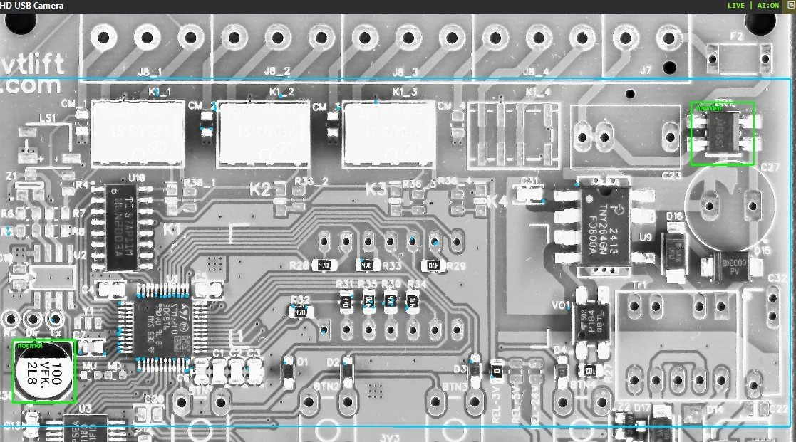
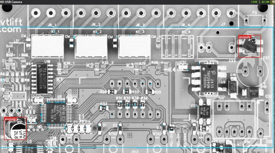
The program identifies chips, component misalignment, assembly errors, and foreign objects.
The neural network determines the type, color, or variant of the product for sorting.
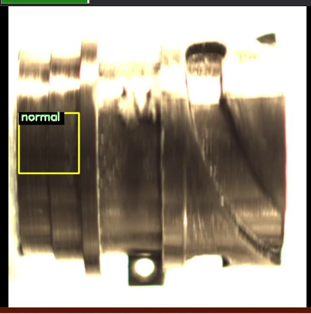
The neural network determines the angle of the product from 0 to 359 degrees, with a resolution of 1 degree.
One model checks hundreds of areas on a printed circuit board, and each area has its own "normal" state.
The program locates the circuit board on the conveyor belt, allowing for shifts and rotations of up to 180 degrees.
Training with a limited number of images
Typically, training a neural network requires thousands of labeled images. In engiAI, the operator takes a few pictures of the product, and the program automatically creates the training dataset. The program shifts and rotates the area, adjusts brightness and contrast, adds mirrored copies, and organizes the images into classes. For printed circuit boards, the program automatically generates synthetic defects by shifting a component along with the actual texture of the board. This process allows the creation of hundreds of training images from a single picture.
The training process is initiated with a single button. It can be performed either on an NVIDIA graphics card or on the processor. The entire cycle, from "showing the product" to "training the model" and "system operation," is handled by a technician or line operator, rather than a specialized machine learning expert.
Cameras and outputs
| What can be connected | Features |
|---|---|
| Hikrobot cameras | GigE and USB3 industrial cameras: exposure time, gain, resolution, discrete inputs and outputs. |
| SICK picoCam cameras | Industrial cameras IDS uEye: exposure time, gain, output to an actuator. |
| USB and IP cameras | Webcams and surveillance cameras using the RTSP protocol. Even a smartphone camera can be suitable for a pilot project. |
| Sensors and Encoders | The image is captured based on a sensor signal, and the variation in the capture time does not exceed 4 milliseconds. The rejection process is synchronized with the conveyor encoder. |
| Outputs | The system sends data to a robot or PLC controller via TCP/IP, controls a discrete output to activate a pusher or lamp, and provides an audible signal. |
| Scalability | A single program can manage multiple cameras simultaneously, with up to 20 neural network models per camera. "Camera and model" configurations can be switched with a single click when changing products. |
06Stereoscopic Vision: Height and Dimensions in 3D
One camera provides a flat image. When the robot needs to determine height, for example, the top of a stack of boxes or the level of a product in a container, a stereo vision system is connected.
Two cameras view the scene with a slight offset, similar to human eyes. The software uses the difference between the two images to create a depth map and calculates the height, length, and width of the box in millimeters, as well as the distance from the camera to the top of the box. The system can use two industrial cameras from SICK, two USB cameras, or a single stereo module, which is a camera with two lenses.
H The height of the box above the table, in millimeters.
L, W Length and width of the top surface of the box.
Z The distance from the camera to the top of the box. When the camera is mounted on the robot's head, this distance limits the range of motion of the axes.
3D Depth Map: Each pixel in the image is assigned a distance value, and the box appears to rise above the surface of the table.
What the stereo vision system can do in our system
- Calibration using two methods. Precise calibration is performed using a chessboard pattern. A simplified setup can be achieved without the chessboard, using only the distance to the table and a single reference box.
- Laser dot projector. The projector adds a pattern to plain surfaces, making the depth map more detailed. Separate settings are stored for the laser mode and the mode without the laser.
- Camera mounted on the robot's head. The Robot1 program takes into account the robot's current head height and recalculates the measurement, adjusting for any vertical movement.
- Height restrictions. For each distance range from the surface, there are height limitations for the robot's axes. The higher the stack, the less the robot is allowed to lower itself, and the suction cup does not press down on the cardboard. These rules apply to all sources of movement for the robot.
- Protection with outdated data. If the camera data is outdated, the axes specified in the settings will not move. This behavior can be disabled in the settings.
| Test bench check | Result |
|---|---|
| An inexpensive stereo module: two 1280 x 720 pixel sensors, with a distance of approximately 60 mm between the lenses, and the camera positioned at a height of 255 mm. | The measurement error for the height of a box is between 1 and 3 mm, without using a laser or a checkerboard pattern. |
| The same stereo module in a simplified configuration. | The error in measuring length and width is approximately 10%. Accuracy improves with a laser projector and calibration using a checkerboard pattern. |
07Robot1: Controlling the robot from a computer
Robot1 controls the industrial robot directly over the network via the robot controller. No separate software from the robot manufacturer is required. The robot's teach pendant remains for enabling the operating mode and for emergency stops.
| Function | What this provides |
|---|---|
| Manual control | Each axis is controlled by buttons that allow the user to select the step size and speed. The robot's head moves strictly vertically and in a straight line, while the part in the gripper maintains its orientation. |
| Poses and Cycles | Poses can be saved with a single click and combined into a cycle with the desired speed, pauses, and number of repetitions. |
| Packing into boxes | The operator specifies the number of parts per row, the spacing, and the number of layers, and the program calculates the position of each location. The box is adjusted to match the actual robot. |
| Inputs and Outputs | The pneumatic gripper is activated in the gripping pose. Cycles are started and stopped by signals from sensors. If a sensor does not detect a part after gripping, the robot repeats the gripping action or stops. |
| Limitations | The program defines soft limits for the axes, prohibited zones, speed limits, and a button for smooth stopping that clears the command queue. |
| Commands from the vision system | The program receives commands over the network. For each axis, you specify the command, speed, offset, and direction, and each class has its own defined path. |
| Operation without a computer | The completed program cycle is downloaded to a USB drive as program files for the teach pendant, and the robot executes it independently. |
| Projects and Log | Everything related to a specific application is stored in a single project file. The log records each command sent to the robot. |
Stend digital twin
In the Stend module, the robot, the box, the pick-and-place operation, and the part itself are arranged on a three-dimensional scene using a mouse. The gripper is assembled from a support, a beam, and suction cups directly on the model. The software calculates the reachability, the stacking plan, and the cycle time, and then displays the entire cycle with simulations of sensors and pneumatics.
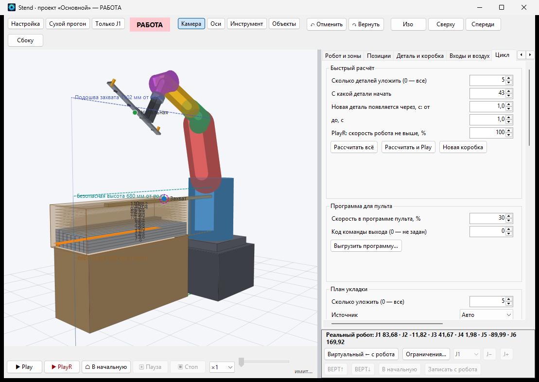
The transition to actual operation is performed in stages. First, the cycle is demonstrated on a model. Then, a "dry run" records the steps in a log without sending any commands to the robot. Next, the robot moves only one axis at a speed not exceeding 5%. Finally, the complete cycle is initiated, with point confirmation and a speed limit.
08All of the software is our own development
The engiAI and Robot1 programs were developed by specialists at "Vector Technologies." This translates into several practical benefits for you.
If a task requires a new function, a new communication protocol, or a new report, we implement it ourselves.
The vision system, communication, and robot control are all managed by a single team, which means issues are resolved without having to correspond with multiple vendors.
Image processing is performed on a computer located on the production line, so your production images never leave the facility.
The programs are available in Russian, English, German, French, Spanish, Italian, Portuguese, Chinese, Japanese, Korean, Hindi, Arabic, Indonesian, and Vietnamese.
Operation logs and a software database store the history of trigger events. This data is suitable for defect statistics and analysis of line performance.
The second identical unit is started by copying the project and the neural network model, rather than creating a new integration project.
| Requirements | Value |
|---|---|
| Computer | Windows 10 or Windows 11, 64-bit. A NVIDIA graphics card accelerates training and analysis; without it, the program runs on the processor. |
| Robot | Today, Robot1 controls BORUNTE robots using the HC1 controller. Robots of other brands, as well as PLCs, receive commands from engiAI over the TCP/IP network. |
| Trial version | The programs can be downloaded from the website engi.live. Without a license, each program functions for 20 minutes. |
09About Vector Technologies
"Vector Technologies" is a developer, manufacturer, and supplier of equipment for industrial automation, based in Minsk. The company provides a full range of engineering services, from project development to commissioning.
Company projects
Machine vision and robotics
- Adapting an industrial robot to the position of an object using machine vision.
- 3DStereo: A contactless method for measuring dimensions using two cameras.
- Automated analysis of printed circuit boards.
- Tablet inspection by zones.
- Packaging control system for pharmaceutical products.
- Automated inspection of labeling.
- Cable and wire marking and insulation control.
Production automation
- AGV system for transporting spools and coils of wire, with a load capacity of up to 2,900 kg.
- Modernization of a bimetallic strip cutting line.
- Comprehensive modernization of the bimetallic strip quality control line.
- Modernization of the vacuum furnace control system.
- Water treatment, preparation, and bottling system for drinking water.
- Testing rig in the Belshina JSC laboratory.
- Automated washing station.
The project descriptions are available on the website vec-tech.by in the "Projects" section.
The company manufactures VTD series frequency converters with power ratings from 0.4 to 630 kW, and VTD20 series frequency converters with power ratings from 0.75 to 15 kW, as well as soft starters with power ratings from 11 to 600 kW, geared motors, control panels, and electronic devices, all produced on our own SMT and DIP production lines. "Vector Technologies" is an official distributor of YASKAWA, SICK, WEG, VIPA, and FATEK. We design automation systems, process control systems, and control panels based on your specifications and provide the necessary documentation for on-site installation. Equipment delivery to your country is discussed on a case-by-case basis.
10 Where is this used, and how is the benefit calculated?
| Industry | What we automate |
|---|---|
| Packaging and logistics | Box orientation and stacking, palletizing, sorting, and dimensional measurement using a stereo camera. |
| Pharmaceuticals | Tablet inspection in blister packs, packaging and labeling control, and rejection. |
| Electronics | Inspection of printed circuit board assembly using the ZONE-PAIR method: checking the presence, alignment, and orientation of components. |
| Machine building and metalworking | Loading machines and presses, inspecting parts, and loading parts into containers. |
| Cable manufacturing | Inspecting markings and insulation, transporting spools using automated carts. |
| Food and beverage industry | Monitoring product flow on the conveyor belt, detecting dropped containers, and sorting. |
| Warehouses | Palletizing and de-palletizing, measuring the dimensions of goods. |
Advantages of a robot with vision over traditional automation
- No expensive tooling is required. Fixtures, supports, and vibration feeders are not needed for each product because the robot adapts to the part itself.
- Reconfiguring the system takes hours. For a new product, a new model is trained and new processing sequences are defined, while the underlying cell mechanics remain the same.
- Small production runs become profitable. When retooling costs are minimal, it becomes profitable to automate even production runs of just one shift.
- One camera performs three functions. The camera guides the robot, checks the quality, and controls the rejection process.
- The system operates under real-world conditions. If a part is misaligned or a batch arrives with a different color, the robot with vision continues to work because it focuses on the part itself, rather than relying on coordinates.
11How to get started
How we calculate ROI
We calculate the return on investment based on your data. To calculate the ROI, we need the data from the table below, and the result will be included in the commercial proposal.
| Data from you | What follows from them |
|---|---|
| How many employees are involved in the operation per shift, and how many shifts are there per day? | How many working hours per year are replaced by a robot? |
| The cost of one hour of labor, including taxes. | Annual savings on labor costs. |
| The defect rate and the cost of each missed error. | Savings from automated quality control. |
| How often the product changes per month, and how long does the setup process take? | Savings on tooling and downtime. |
| The cost of the cell or area required for your application. | Payback period: the cost divided by the annual savings. |
The engiAI and Robot1 programs, along with their manuals and videos, are available on the website engi.live. Without a license, each program functions for 20 minutes.